What you will learn in this articleIn the following article, we present a finite element analysis (FEA) of a load-bearing truss frame carrying a large load from heavy machinery. The simulation identifies the actual load paths, the stress distribution, and the critical components of the structure in the weldable frame constructions.This study shows how the simulation can be used to obtain reliable confirmation of the load capacity, the structural stiffness, and the safety factor of the construction with real loading conditions, ultimately yielding clear opportunities for targeted improvement of the design for an increased structural performance. Learn how you can leverage FiniteNow simulation consulting s to easily transform a CAD model and a design question into clear, useful results for structural optimization and design validation. |
Project Overview
In this example, we’ll take an overview of a load-bearing truss frame that has been designed to hold and support heavy machinery used in industry. The truss frame also provides sufficient clearance for personnel to access the area to install and/or perform service/maintenance tasks on the machinery. The frame is composed of two welded planar steel frames (the main supports) with the lower frame being strengthened via cross-bracing to increase its stiffness and help distribute loads more efficiently.
Additionally, the two frames are linked by inclined trusses that form “V” shaped bracing components that are bolted through welded flanges. These bolts allow the entire structure to be disassembled for ease of transportation and reassembly on-site, which is typical of many large-scale industrial support assemblies.
Finally, the entire construction is mounted onto four vertically-oriented linear actuators, allowing the structure to be moved up/down in a controlled manner. Therefore, the system is appropriate for various uses, including machine support frames, adjustable equipment platforms, or mounts for heavy machinery.


Engineering Challenge
The structural frame needs to be able to support extremely heavy industrial equipment while providing adequate stiffness to position the equipment precisely during normal operation. In this specific application, the equipment module is positioned asymmetrically, causing a significant eccentric load condition, thus generating both vertical load and increased bending within the supporting truss members.
Therefore, the primary problem to solve is to determine whether the truss frame and welded support assembly can safely carry this non-symmetrical load without suffering from either excessive stress or deflection. The key goals of the analysis are:
- to prove that the truss frame and associated welding can withstand the load,
- to identify the most heavily stressed structural members,
- to evaluate the degree of deflection and overall stiffness of the frame;
In addition to the above, the simulation should help identify potential design optimization opportunities, such as reinforcing heavily stressed members or eliminating unnecessary material in low-stress areas.
Simulation Methodology
The structural truss frame has been evaluated using finite element analysis (FEA), with respect to stresses, load paths, and deformations due to operational loading. As the structural members are manufactured from hollow steel sections and plate elements, the geometry was modeled using shell elements; this approach provides an efficient way to model thin-walled structural elements while maintaining accurate representations of both membrane and bending stresses.
The bolted flange connections between the planar frames and the inclined truss members are not explicitly modeled; the connected surfaces have been tied together using tie constraints, which will allow for complete load transfer across each interface while minimizing computational expense.
If you want to learn more about how FiniteNow can help you with simulating screwed connections correctly, make sure to visit our blog post and wiki:
How FEA Reveals Critical Failures in Bolted Connections
Modeling Screwed Connections in Finite Element Analysis (FEA)
Shared nodes were used to model the welded joints between the structural members; this modeling method will allow for the extraction of the grid point forces, which may then be used to determine the forces being transmitted through individual weld lines.
In order to capture realistic load transfer, the grid structure was modeled explicitly. The actual machine itself was modeled as a rigid body, simulating the mass and high stiffness of the equipment while avoiding unnecessary geometric complexity. All components have had gravity loading applied to them in order to simulate the operational weight of the system.
Structural members were assigned structural steel material properties, including elastic modulus, density, and yield strength. Boundary conditions were applied to the model by fixing the upper interfaces of the vertical linear guides, which represent the connection to the actuator system supporting the structure.
Results of the Structural Analysis
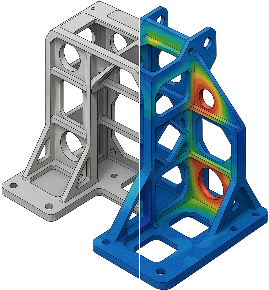
The finite element simulation has provided detailed insight into the stress distribution and load transfer within the truss frame under the defined eccentric machinery load case. Most structural members are operating well below their allowable stress limits, indicating that the overall structural design provides adequate stiffness and load-carrying capability to resist the specified load.
However, the analysis does reveal localized regions where the desired safety factor of 3 is not being met. These local regions appear in orange in the stress visualization. The most critical locations are the T-junctions where the cross bracing connects to the lower primary frame beams. At these locations, the majority of the heavy machinery’s weight is being introduced into the system; however, the load path must cross over the T-junction prior to being absorbed by a vertical support beam (the V-shaped beams).
In addition, the V-shaped truss members themselves also exhibit elevated stress levels, which indicate that these diagonal members are carrying a large portion of the vertical and bending loads generated by the eccentric mass of the machinery. This behavior suggests that the current load path is relying heavily on these diagonal members to transfer forces from the lower frame to the upper frame.
Aside from the localized effects, the remainder of the structure, including the upper frame and actuator interface beams, appears to have considerable unused load-carrying capabilities. The difference in load distribution between the various parts of the structure indicates that the structure would likely benefit from a modified load path that makes use of the available stiffness of the entire frame system and reduces the stress concentrations occurring at the critical welded junctions.

Elevated Stresses (orange) for cross-bracing and V-trusses.

Improved Loading Capacity through clever design adaptation.
Design Optimization
As a direct result of the simulation data, we have developed a design for improving the load path and reducing critical stresses within the structure. A major issue in the initial design was the two V-shaped diagonal members per side creating high-stress conditions in the horizontally loaded members; those members were subjected to very high bending forces as a result of the long lateral distance between the force introduction and the V-shaped bracing.
To correct this condition, the design was altered to only include a single, centrically placed V-shaped diagonal member per side; the wall thickness of that member was increased by 50%. This change allows the loads to travel more smoothly through the structure. With the thicker V-shaped member positioned directly in the center of the structure (and located directly in the global load path), a higher percentage of the applied loads will be transferred to the top frame, which had been subject to much less load than the bottom frame. Therefore, the loads that enter the bottom frame will be more uniformly distributed, greatly reducing the high stress concentrations previously seen at the T-joints of the bottom frame beams.
Overall, the improved design provides multiple benefits simultaneously. First, the stress levels in the critical areas of the structure are lowered, thereby allowing the structure to meet the target safety factor. Second, the number of individual parts in the structure has been decreased, which will make manufacturing and assembly easier. Finally, the reduction in the number of parts will result in an overall lighter structure, thus reducing the amount of materials required to build the structure, and ultimately the cost of the materials while still maintaining the structural integrity. Therefore, the example above illustrates how simulation-based design insights can result in more intelligent structural designs. By better understanding the true load distribution throughout the frame, engineers can both strengthen the structure where necessary, while eliminating unnecessary complexity, resulting in a safer, simpler and more cost-effective design.
Value of FEA for Truss Structures
In this example, the value of using Finite Element Analysis (FEA) was to understand actual load paths in trusses. Although the original design looked like it would work structurally, the simulation showed areas of high localized stress and poor load distribution that would have been difficult to see just looking at simple calculations.
By showing how the forces were flowing through the frame and the stresses being developed in each area, we could find which were the weak points of the design and which areas needed to be improved. Using this type of data allowed us to optimize the design, making it stronger and less complicated. The new truss structure is more efficient; it has fewer parts, better load distribution throughout the entire frame, a greater strength-to-weight ratio, and a lower manufacturing cost.
Examples of this type of improvement show how Simulation can help make more informed design decisions. It gives engineers the ability to modify designs based on actual structural performance instead of relying solely on conservative assumptions.
A Faster Path to Reliable Structural Simulation with FiniteNow
To determine if a truss frame can support a given load or to determine which members of the frame are the most susceptible to failure due to various loadings requires a well-thought-out modeling strategy and a good definition of what you want to simulate. FiniteNow offers a structured digital workflow that enables engineers to outsource simulation projects quickly while maintaining complete clarity about the associated timeline and costs.
Using FiniteNow’s simulation project assistant, users can define the structural analysis project they want to execute in a series of straightforward steps. First, users can provide a short description of their required project. For instance, determining the load-carrying capability of a truss frame, evaluating the stiffness of a frame or truss, or optimizing a truss frame for minimal weight. Users may also include relevant information related to their project, such as their CAD file geometry, anticipated load cases, and desired product output (i.e., stresses, displacements, or safety factor).
Once the above information is entered, the system will guide the user through the relevant project parameters. These include the selection of the material properties to use in the simulation, and the identification of the different simulation phases (modeling concept, simulation, documentation) that need to be executed. In addition, if preferred, FiniteNow engineers will provide recommendations regarding the best solver and model strategy to employ based on the user-defined problem.
Then, our tool will automatically produce a comprehensive project plan and estimate for the proposed project. The plan will define the scope of the simulation, the load cases to be analyzed, the evaluation criteria, and the desired outcomes from the simulation. Afterward, you will be connected with our simulation experts to prepare the next steps.
Following confirmation of the project, experienced simulation engineers will execute the simulation according to the previously agreed-upon methodology. This will include preparing the geometry for the simulation, generating the mesh, defining the boundary conditions and loads, executing the solver(s), and verifying that the solution is stable. The results will then be reviewed to identify the locations of highest stresses, load paths, and opportunities to improve the design of the structure.
Once completed, the results of the simulation will be presented to the client in the form of a concise engineering review along with a written report describing the assumptions that were employed during the simulation, key findings, and recommended modifications to the design. By employing this methodology, FiniteNow enables its customers to convert complex structural analysis problems into clearly defined and transparent simulation projects that can be initiated in minutes.
FiniteNow will create an instant quote based on your input in minutes.

Every work package is clearly broken down with tasks and deliverables, ready to be ordered.
Added value through FiniteNow at a glance
- Immediate price indication & clear proposal: Early cost transparency and defined deliverables instead of open-ended estimates.
- Structured project flow: Fixed briefing, clear milestones, short reviews—less idle time and fewer misunderstandings.
- Up-front clarification of critical items: NDA, model rights/licenses, target metrics, variants, and reporting formats are resolved before any costs are incurred.
- Transparent assumptions & records: Documented sources, sensitivities, and parameter tables; results are shareable and auditable internally.
- Reusable setup: A consistent structure for input, evaluation, and reporting that simplifies follow-on studies and comparisons.
- Reliable communication: A single point of contact and a defined feedback cadence.
- Data and compliance security: NDAs, clear purpose limitation, and license checks for supplied models and data.
Thus, a concrete question – “Does my truss structure have sufficientl load-capacity?”—becomes a well-structured project with transparent costs, a traceable approach, and robust results. Try it our yourself now: FiniteNow’s instant projecting platform for engineering simulation.
Simulation Work Reinvented