
What you will learn in this articleBolted connections are among the most widely used joining methods in engineering, valued for their strength, reversibility, and reliability. Their correct design and validation are therefore essential for ensuring structural integrity, safety, and performance. Below, you will learn how simulations help your company achieve more robust and reliable designs.The article guides you through state-of-the-art screwed connection design via an exemplary flange simulation, highlighting common pitfalls and the advantages of having our FEA experts analyze your project. |
Where to start – Bolts 101
Before plunging into the means & benefits of structural simulations, let’s swiftly revisit the key concepts about screwed connections.
Advantages of Bolts
- Reversible Connection
- High Strength
- High Temperature-Resistance
Dimensioning & Validation of Bolted Connections – When to use What
The classical engineering approach to designing and verifying a bolted connection is the application of standards. A prominent example is the widely recognized engineering guideline VDI 2230, the European standard for the systematic calculation of bolted joint systems. Owing to its structured methodology, it has proven to be an invaluable tool for the sizing and verification of bolts and screws.
However, this formulaic, hand-calculation-based approach has its limitations. In addition to being tedious and prone to error due to the large number of required calculations, its applicability is highly restrictive. In order to fit a unified analytical formulation, the bolted joint must exhibit a very simple geometry, and the applied loads must be easily transferable to the individual screws. This makes the approach impractical – if not insufficient – for many modern component designs.
Fortunately, there is a solution. Numerical simulations can alleviate these restrictions, expanding the range of applicable geometries and loading conditions while also increasing accuracy. Both as a standalone tool but also as an enhancer for well-established standards. In the following, we demonstrate how this can be achieved.
What is Pretension in Bolted Connections?
Pretension is one of the most important aspects when designing and evaluating a bolted connection, regardless of whether it is hand-calculated or simulated. Pretension describes the axial force with which the bolt loads the connected components. It is created through the tightening of the bolted connection, which elongates the screw and thus stresses it.
A large pretension has multiple significant benefits for the connection. For example, the clamping force itself can ensure that the frictional force is high enough to prohibit any sliding of the connected components. Additionally, it can be used to ensure that there is no cleavage of the components, which is essential for sealing. Furthermore, the pretension influences how external loads propagate through the connection by biasing the load path toward the components rather than the screw itself, which can further increase the maximum strength of the joint.
However, it must be ensured that the screw itself is able to withstand the pretension in combination with the external load case. In addition, the pretension can be altered by changes in temperature and creep over time, requiring special care during the validation process. Lastly, it should be emphasized that pretension often loads screws into post-elastic behavior, transforming the analysis into a complex, non-linear problem, which can only be properly depicted through simulation.
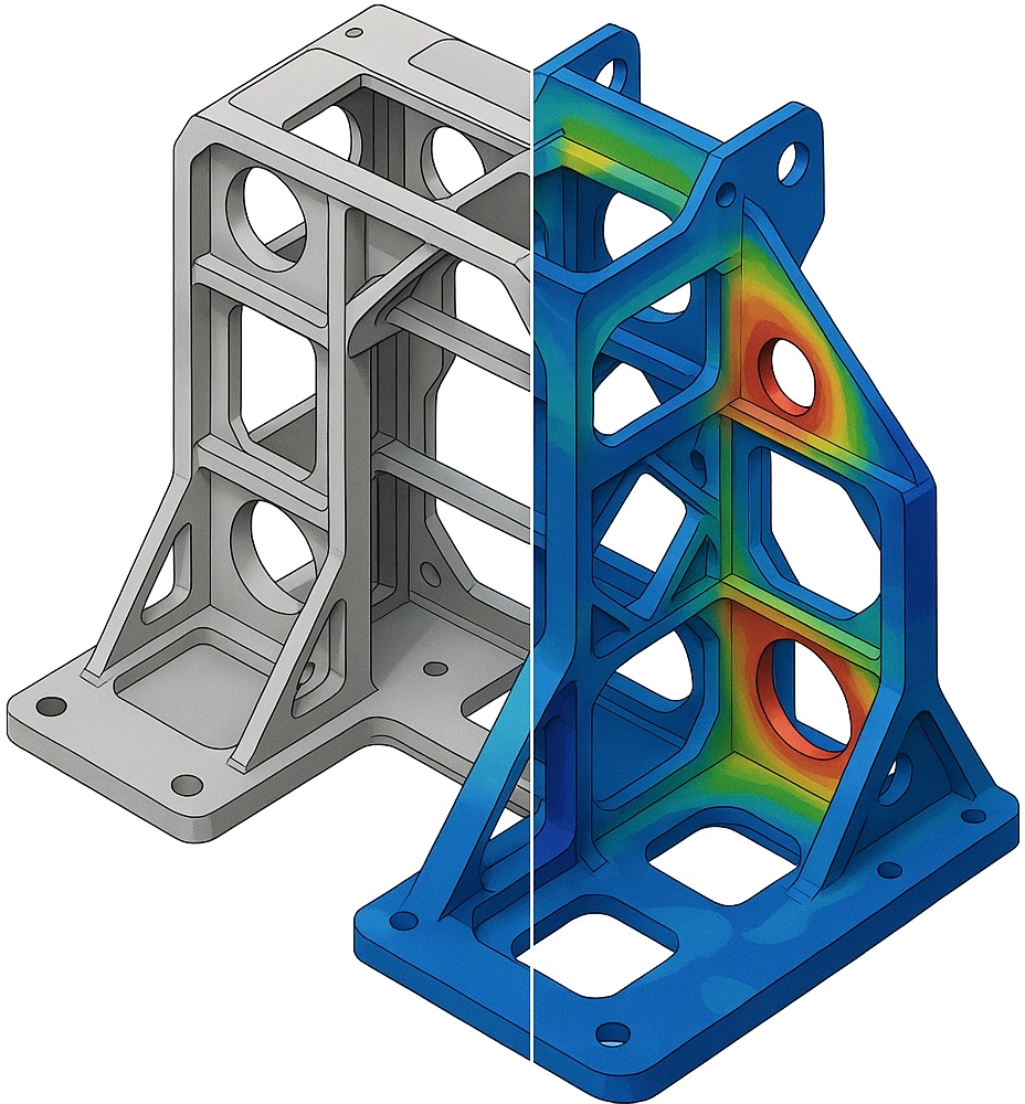
How Finite-Element-Analysis works for Bolted Joints

Overview

Mesh (tetrahedral and hexahedral)
Let us now dive deeper into how we can best leverage the power of simulations to make screwed connections safer and more performant than ever. Our expert simulation consultants here at FiniteNow have analyzed this hydraulic valve with its flanged connection under an unusual load case: while valves are usually only subjected to high internal pressure loads, it was necessary here to also investigate the effect of one ton of force acting on the component and creating large moments due to its structural integration under cyclic loading.
As with any liquid container, it is not only essential to withstand the high forces, but also critical to avoid any cleavage, which would risk a loss of sealing capability.
What important Metrics need to be assessed:
• Maximum Bolt Force & Moments
• Connection Contact Status & Pressure
While VDI 2230 provides answers to both of these points of interest, we will see how this results in an incomplete picture and why you are better off having your bolted connections analyzed by our simulation service here at FiniteNow.
FE-Simulation Setup
The simulation utilizes CAD files of both sides of the valve casing flanged together via four model screws. The screws feature a structured hexahedral mesh, while the casing is discretized with a free tetrahedral mesh. Through the exact modeling of all components, we can account for their unique geometries, whereas calculation standards can only factor in shapes through integrated model scalar stiffnesses, resulting in restrictive input data for connection evaluation. Garbage in, garbage out.
For the materials, we have used the correct cast aluminum alloy for the casing and an appropriate steel alloy for the screws, featuring detailed, non-linear stress–strain curves that would be impossible to account for in hand calculations.
One imperative aspect when simulating screws is the correct assignment of contacts. For one, when cleavage is of interest, it is necessary to use a separable contact between the joint components. The casing sides are brought together via a frictional contact with a friction coefficient of 0.1. Likewise, it is important to model the screw interfaces appropriately.
A common simulation mistake is to bond the entire screw head and shaft to both components. In reality, however, screws have a threaded connection to one side, and on the other side they are only in contact via the screw head and not the shaft, due to the clearance boreholes. This is usually done incorrectly when automatically creating contacts, as can be seen in the picture below.

Incorrect, auto-generated Contact

Corrrect, screwhead-only Contact
The loading of the component needs to be split into two separate steps. First, applying the pretension and locking the created state, and only secondly applying external loads. This reflects the chronological order of real-world systems, where, of course, first a screw is tensioned during installation, and only afterward do any forces act on the system.
Neglecting this detail will result in the finite element solver setting the pretension to the specified value while simultaneously linearly ramping any applied forces, thereby falsifying the results. Another reason why it makes sense to outsource your project to FEA services that are well-seasoned in accounting for every detail, like ours at FiniteNow.
The external forces are modeled in accordance with the specified requirements, featuring a fixed support on one side of the casing, a lateral force of one ton on the other side, and an internal pressure of 30 bar. A pretension of 8kN per screw is applied.
All that is left now is to specify appropriate solver settings and press go.
Results: What Calculations would have missed
The stresses created through the applied loads were insignificant, as expected for such a large cast aluminum component. This can also be seen in the left picture below. Likewise, the forces acting on the screws specifically are also below their specified ratings. An inexperienced simulation engineer could thus pass the setup as acceptable.

von-Mises Stress
 - FiniteNow")
Deformation, 400x upscaled. Visible cleavage
However, when investigating the deformation (picture: right), we obtain the first hint of a problem: a small cleavage is occurring. This can be extracted more deliberately when examining the contact status between the casing halves. The lateral force is not sufficient to create structural failure, but it can pry open the contact surface. The screw setup does not provide sufficient clamping.

Contact Status showing the same Cleavage
Why is this problematic? The medium could simply leak out of the small slit, making this a severely safety-critical failure mode. Fortunately, our experts caught it.
What would the VDI 2230 say about this failure mode? Even though it is also able to predict cleavage, the complex geometry of such a cast casing, together with the strong bending moments created through one ton of side load, would prevent it from confidently inferring cleavage—especially since it is only able to act on aggregated metrics. Through our simulations, however, we can directly infer the contact status over the entire surface.
Does that mean calculation standards are all bad? Of course not. Standards rely on vast amounts of experience accumulated into proven formulas that account for both the underlying physics and countless experimental studies. Even though they are not as versatile as simulations, they can be used together to achieve the best of both worlds. By extracting the screw forces from simulations and plugging them back into the VDI 2230 formulas, we obtain a robust framework well-suited for virtually every application.
Why You Benefit from Hiring Simulation Experts
Simulation is no longer an alternative to classical engineering hand calculations. It is no mere option. Simulation has distinguished itself as an irreplaceable tool that not only makes designs safer and more reliable by spotting challenges other methods would not, but also allows systems to be designed in a more performant way, ensuring you stay ahead of the curve.
However, even this simple example poses many pitfalls that only an experienced simulation engineer can avoid. Here lies the problem: an unavoidable tool that is too complex.
FiniteNow to rescue! We enable you to harness the benefits of simulation while keeping it accessible, cost-effective, and flexible.
Get support from true consulting experts in strength analysis with special focus on contact modeling, such as screwed connections, welding, bonding, and many more. There is no need to harbour all these competences in-house at all times. We are flexible and accessible at lightning speed. Making sure you can have the best quality in FEAs whenever and only when you truly need them.
Get started with our Instant-Quoting-Tool right now to see for yourself how easy it is to get the support you require within mere minutes. No waiting. No compromise.
Below you can see how our tool lets you set a course on what you need, and we take care of the hard part – actually getting there. You will have transparent access to our proposed roadmap, timeline, and pricing, giving you maximum control over the process.
Our expert simulators are ready to support you personally in your endeavours at any time at the press of a button.

If you want to read more about how we accelerate your business, make sure not to miss out on our blog post all about it:
2025 Will Change the Way you Engage Simulation Engineers for FEA and CFD
Simulation Work Reinvented