

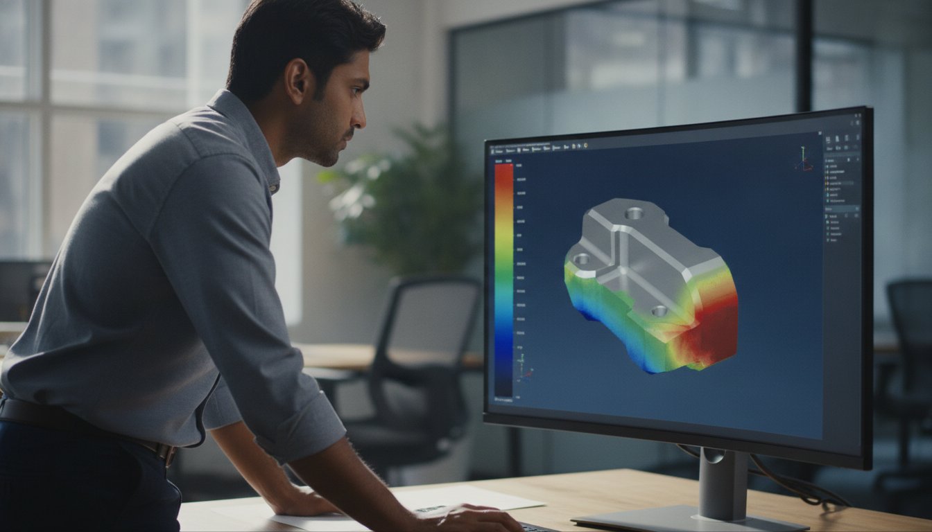
A single sharp corner in your CAD model can turn a high-fidelity simulation into a collection of mathematical lies. You’ve likely experienced the frustration of a mesh refinement that sends stress values toward infinity while your physical intuition suggests stability. This “singularity trap” is a primary reason why many simulations fail to predict real-world fatigue. Effective stress concentration analysis isn’t just about finding the red spots on a plot; it’s about distinguishing between physical reality and numerical artifacts.
We understand that inaccurate results lead to costly physical test failures and wasted engineering cycles. This guide provides the technical framework needed to master the mechanics of stress risers and ensure your FEA results are both credible and actionable. You’ll learn how to navigate geometric singularities, implement ASME V&V 10-2019 principles, and achieve reliable fatigue life predictions. We’ll show you how to optimize geometry for minimal weight while ensuring every design is validated and ready for production without the burden of legacy software costs.
Key Takeaways
- Identify critical “stress risers” like fillets, holes, and keyways to understand how localized geometry dictates the structural integrity of your design.
- Distinguish between theoretical stress concentration (Kt) and the fatigue notch factor (Kf) to improve the reliability of your fatigue life predictions.
- Master the mesh singularity trap in stress concentration analysis to distinguish between mathematical artifacts and genuine structural risks.
- Implement industry-specific validation protocols for high-stakes applications, including thin-walled aerospace composites and medical-grade biomechanics.
- Optimize your engineering workflow by replacing heavy software licensing costs with on-demand simulation services and instant quoting.
Understanding Stress Concentration: The Mechanics of Structural Failure
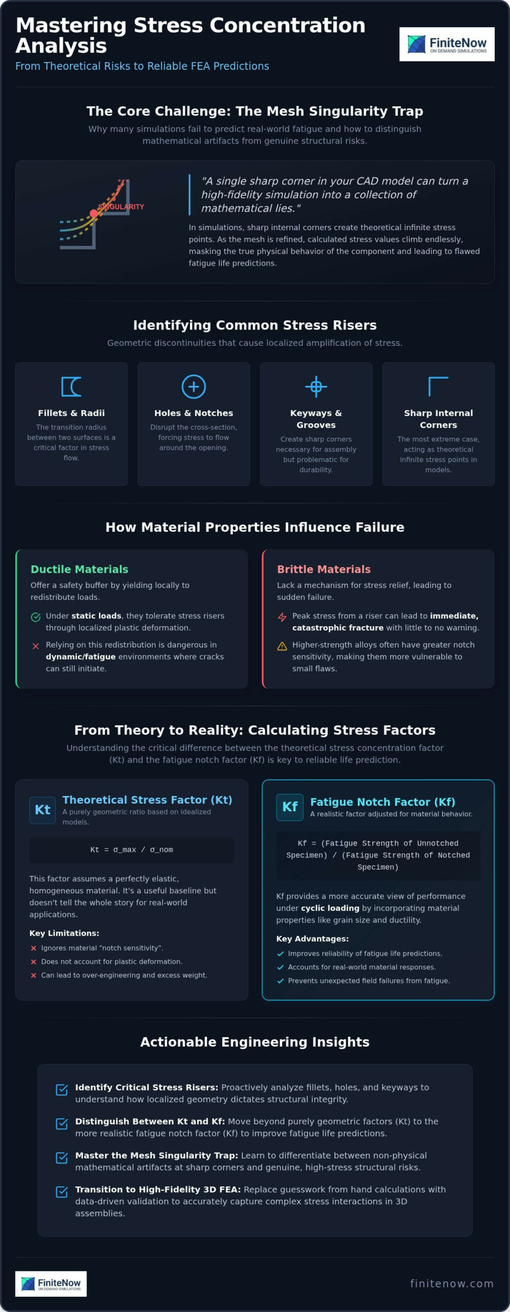
Stress concentration analysis is the cornerstone of structural integrity. It identifies why a component fails at a specific point rather than across its entire cross-section. Geometric discontinuities, or “stress risers,” cause a localized amplification of stress that can lead to premature failure. Common culprits include fillets, holes, keyways, and sharp internal corners. In these zones, the actual stress significantly exceeds the nominal stress calculated by basic hand formulas.
The relationship between peak stress and nominal stress depends heavily on material properties. In brittle materials, the peak stress often leads to immediate, catastrophic fracture because there’s no mechanism for stress relief. Ductile materials offer a safety buffer; they yield locally to redistribute the load. However, relying on this redistribution is a dangerous strategy in dynamic environments. Stress concentrations remain the primary drivers of fatigue-related failures in mechanical assemblies, initiating microscopic cracks that propagate until the structure reaches its limit state.
The Physics of Geometric Discontinuities
Imagine stress as a fluid flowing through a part. When this “flow” encounters an obstacle like a hole or a notch, the lines of force must compress to navigate the geometry. This compression creates a high-density stress zone. Understanding Stress Concentration requires recognizing that the tighter the radius, the more severe the diversion. Sharp internal corners represent the extreme case, acting as theoretical infinite stress points in linear elastic models. Notch sensitivity also plays a role; higher-strength alloys often possess greater sensitivity, making them more vulnerable to small geometric flaws than lower-grade counterparts. This sensitivity varies across material grades, meaning a design that works in mild steel might fail catastrophically if swapped for a high-strength aluminum alloy without recalculating the risers.
Static vs. Fatigue Loading Considerations
Static loading and high-cycle fatigue (HCF) require different analytical mindsets. Under static loads, ductile metals often tolerate stress risers through localized plastic deformation. The material “softens” the peak, effectively blunting the notch and preventing immediate failure. In HCF scenarios, this doesn’t happen. Every cycle exploits the local peak, driving crack initiation long before the nominal stress reaches the yield point. The Stress Concentration Factor (Kt) is defined as the ratio of maximum stress to average stress. While Kt provides a theoretical baseline, it doesn’t account for the material’s fatigue limit. This distinction is vital for engineers moving from simple static checks to durability validation. High-fidelity simulation is essential because it bridges the gap between idealized formulas and real-world durability, ensuring that local peaks don’t compromise the entire assembly’s lifecycle during your stress concentration analysis.
Theoretical Factors vs. FEA: Calculating Kt and Kf
For decades, engineers relied on Peterson’s Stress Concentration Factors as the gold standard for predicting local peaks. These empirical charts provide the theoretical stress concentration factor (Kt), which is a purely geometric ratio. Kt assumes a perfectly elastic, homogeneous material. It doesn’t account for the “notch sensitivity” of real-world alloys. This is where the fatigue notch factor (Kf) becomes critical. Kf adjusts the theoretical peak based on material grain size and ductility, offering a more realistic view of how a part will actually perform under cyclic loading. Relying solely on Kt often leads to over-engineering, while ignoring the nuances of Kf can result in unexpected field failures.
Modern stress concentration analysis requires moving beyond these two-dimensional approximations. While hand calculations are useful for initial sizing, they struggle to account for the complex interactions found in 3D assemblies. When multiple stress risers are located in close proximity, their stress fields overlap in ways that isolated empirical formulas cannot predict. Transitioning to high-fidelity 3D Structural FEA allows you to capture these interactions with precision, replacing guesswork with data-driven validation.
Hand Calculations and Empirical Charts
Analytical methods and empirical charts are efficient for simple geometries like a single hole in a plate or a stepped shaft. They provide a quick sanity check during the conceptual phase. The risk arises when you interpolate between curves on a non-standard geometry. Small deviations in a fillet radius or a notch depth can lead to significant errors in the calculated Kt. These charts typically assume uniaxial loading. In the real world, components face multi-axial stress states where tension, torsion, and bending occur simultaneously. Empirical data often fails to provide a reliable safety margin in these complex scenarios. Effective design mitigation often draws from broader Industry Applications, where manufacturing constraints must be balanced against structural requirements.
The Shift to Finite Element Analysis
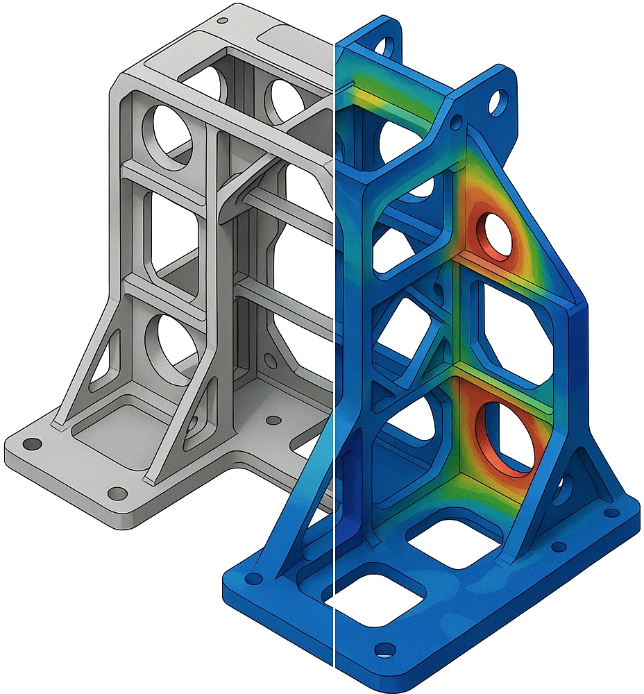
Finite Element Analysis (FEA) has disrupted the traditional reliance on lookup tables. Instead of calculating a single point, FEA generates a comprehensive Von Mises stress distribution across the entire volume of the part. This visualization reveals how stress “flows” around obstacles and where adjacent risers might amplify one another. You can see the gradients, identify potential crack initiation sites, and optimize the geometry to “smooth” the stress paths. To deep dive into these methodologies, see our guide on Structural FEA: The Modern Engineer’s Guide to Stress and Failure Prediction. If your current workflow is bottlenecked by slow manual checks, you can get an instant quote for on-demand simulation to accelerate your validation timeline.
Navigating the Mesh Singularity Trap in Simulation
A perfectly sharp internal corner is a mathematical fiction that breaks standard linear elastic solvers. In the context of stress concentration analysis, this is known as a numerical singularity. As you refine the mesh to capture more detail, the stress at that corner continues to climb toward infinity; it never plateaus. This happens because the mathematical model at a zero-radius notch has no finite solution. Understanding this trap is vital for any engineer who wants to avoid over-designing based on non-physical results. You must distinguish between a real stress peak, which converges to a specific value, and a singularity that grows indefinitely with every mesh refinement.
High-fidelity simulation requires a disciplined approach to mesh density. While a global coarse mesh might miss a critical riser, an overly dense mesh at a sharp corner will yield “red spots” that don’t exist in reality. The goal is to achieve mesh independence where the results remain stable regardless of further refinement. This process is a core requirement of ASME V&V 10-2019, the standard for verification and validation in computational solid mechanics. Following a structured workflow ensures your simulation represents physical reality rather than numerical errors.
Mesh Convergence Study Protocols
To validate your results, you shouldn’t rely on a single run. Start with a baseline simulation using a global coarse mesh to identify general load paths. Once you’ve located high-stress regions, apply local mesh refinement using mesh controls or sub-modeling techniques. The final step is to plot the peak stress against the element size. A valid result will show a convergence plateau where the stress value levels off as elements get smaller. If the curve continues to spike vertically, you’re likely chasing a singularity rather than a physical stress concentration.
Handling Geometric Singularities
When you encounter a singularity, the solution isn’t more mesh; it’s better geometry. Use the “Stress Gradient” method to evaluate the validity of a peak. If the stress drops off by 50% or more across a single element, the result is mesh-dependent. In these cases, you should replace sharp corners with realistic fillets in your CAD model. Even a tiny radius provides the solver with a finite geometric feature to calculate. If the artifact is located far from your primary area of interest, apply Saint-Venant’s Principle. This principle allows you to ignore local numerical noise if it doesn’t influence the stress distribution in the critical sections of your assembly. This targeted focus prevents you from wasting computational resources on non-critical geometric flaws.
Industry Applications: Stress Analysis Across Verticals
Stress concentration analysis isn’t a generic procedure; it’s a domain-specific science that adapts to the physics of each vertical. In the automotive sector, the durability and crashworthiness of chassis components are paramount. Engineers analyze how energy dissipates through the frame during an impact, ensuring that localized stress at weld points or mounting brackets doesn’t cause premature structural collapse. The energy sector faces different hurdles. Wind turbine components and pressure equipment must withstand extreme thermal gradients and cyclic wind loads where a single notch can lead to catastrophic failure. Industrial machinery relies on similar precision for rotating shafts and bolted joints. These components endure relentless vibration. A minor geometric flaw in a shaft shoulder can initiate a fatigue crack that leads to expensive downtime or equipment failure.
To ensure your designs meet these rigorous industry standards, you can submit your project for an instant quote today and leverage our pre-qualified engineering team.
Aerospace and Composites
Aerospace structures push materials to their absolute limits. In thin-walled composite assemblies, managing stress risers in perforated skins and fastened joints is a constant battle. Local stress peaks in laminates often trigger delamination, where the bond between layers fails before the fibers themselves break. This requires a sophisticated understanding of interlaminar shear stresses and buckling modes. High-fidelity FEA allows designers to predict these failure points with the certainty required for flight certification. For projects requiring a multi-physics approach, such as those involving thermal or fluid loads, explore our Coupled-Field Analysis Services. This targeted simulation approach ensures that localized peaks don’t compromise the entire airframe’s lifecycle.
Medical Device Validation
Biomechanics simulation has become a standard requirement for regulatory bodies like the FDA. High-fidelity FEA is essential for predicting the fatigue life of nitinol stents under physiological cyclic loading. These devices must survive millions of heartbeats without structural failure, making even the smallest geometric discontinuity a potential risk. Similarly, load-bearing orthopedic implants feature complex, organic geometries that defy traditional analytical methods. Engineers must validate safety factors across these irregular surfaces to prevent implant loosening or fracture. Precision in these simulations isn’t just about efficiency; it’s about patient safety and passing rigorous validation protocols. By identifying stress concentrations early, medical device manufacturers can avoid the high costs of physical test failures and regulatory delays.
Scaling Design Validation with On-Demand FEA Expertise
Traditional simulation workflows often hit a wall at procurement. High annual licensing fees and the need for specialized hardware create a barrier that slows down R&D. On-demand FEA services disrupt this model by providing high-fidelity analysis without the fixed overhead. This shift allows engineering teams to scale their validation capacity instantly, matching the pace of modern product development cycles. Instead of waiting for budget approval for a new software seat, you can initiate a professional stress concentration analysis immediately.
Leveraging a German-based engineering team ensures your results meet the highest standards of reliability. These experts bring a deep understanding of structural mechanics and regulatory requirements, providing the validation needed for final production. The transition from a raw CAD model to a comprehensive FEA report is streamlined through a digital-first platform. This eliminates the traditional friction of long email chains and vague lead times, replacing them with transparency and speed.
Eliminating Software License Barriers
The ROI of Engineering Simulation Without Software Licenses is clear for teams that don’t require 24/7 solver access. Project-based FEA transforms a capital expenditure into a flexible operational cost. You no longer need to maintain expensive licenses for specialized solvers like Nonlinear FEA, Thermal Analysis, or CFD. Instead, you access these high-end capabilities on a per-need basis. This approach allows you to reserve your internal resources for design iteration while outsourcing the heavy computational lifting to specialists who use the latest 2026 releases of industry-standard tools. It’s a scalable solution that grows with your project demands without increasing your fixed liabilities.
The FiniteNow Workflow
Efficiency is built into every step of the engagement process. You start by submitting your CAD geometry and load cases through the instant quoting system. This platform removes the procurement bottleneck, providing a technical review and a firm price in minutes rather than days. Once the project begins, you collaborate directly with pre-qualified experts via video calls to refine boundary conditions and ensure the simulation reflects your physical test environment. This high-touch interaction ensures that your stress concentration analysis is not just a bunch of colorful plots, but a validated roadmap for failure prevention. Get an instant quote for your stress concentration analysis today and move your design toward production with confidence.
Accelerating Structural Validation through High-Fidelity Simulation
Reliable structural design depends on your ability to separate mathematical artifacts from real-world failure risks. Mastering the mesh singularity trap and transitioning from static hand calculations to high-fidelity 3D models ensures your designs are production-ready. Effective stress concentration analysis requires more than just identifying red spots on a plot; it demands a validated approach that bridges the gap between geometry and material fatigue life.
FiniteNow provides a streamlined alternative to traditional engineering bottlenecks. You don’t need to carry the overhead of expensive software licenses to access world-class simulation tools. Our German-based engineering team provides on-demand structural validation, delivering professional FEA reports that meet rigorous industry standards. This modern workflow removes procurement friction and empowers your team to focus on innovation rather than troubleshooting software errors. Take the next step in optimizing your design cycle and ensure your components are validated for the long term. Get an Instant Quote for Professional FEA Services and start your project today.
Frequently Asked Questions
What is the difference between stress concentration and stress intensity?
Stress concentration refers to the localized increase in stress due to geometric features like holes or fillets in a continuous material. Stress intensity is a fracture mechanics term that describes the stress state specifically near the tip of a sharp crack. While stress concentration analysis evaluates the risk of crack initiation, stress intensity factors determine if an existing crack will propagate to failure.
How do I know if my FEA stress peak is a real failure point or a singularity?
Perform a mesh convergence study to distinguish between physical reality and numerical noise. Real stress peaks will plateau at a specific value as the element size decreases. In contrast, a mathematical singularity at a perfectly sharp corner causes the stress to increase infinitely with every refinement. If your results don’t converge, you likely need to add a realistic fillet radius to your CAD geometry.
Can I use hand calculations instead of FEA for stress concentration analysis?
You can use classical analytical methods for initial sizing and simple geometries like stepped shafts or plates with holes. However, hand calculations fail to capture the interaction between multiple adjacent stress risers or the effects of multi-axial loading. For complex 3D assemblies and safety-critical components, high-fidelity FEA is required to provide the precision needed for regulatory validation and fatigue life prediction.
Why does mesh refinement sometimes lead to higher stress values?
Finer meshes allow the solver to capture steep stress gradients that a coarse mesh would simply average out. In a well-defined model, this refinement leads to a more accurate peak value that eventually stabilizes. If the stress continues to climb without reaching a limit, you’ve encountered a geometric singularity where the mathematical equations lack a finite solution at a zero-radius transition.
How does material ductility affect the impact of stress risers?
Ductile materials can tolerate higher stress concentrations under static loads because they yield locally to redistribute the force across a larger area. This blunting effect provides a safety margin that brittle materials lack. Brittle materials don’t deform plastically; they fracture almost immediately once the peak stress exceeds the material’s strength. This makes stress concentration analysis particularly critical for high-strength, low-ductility alloys.
What industries require formal stress concentration validation reports?
Formal validation reports are mandatory in safety-critical sectors like Aerospace, Medical Devices, and Energy. Regulatory bodies such as the FDA and FAA require documented proof that structural risers won’t lead to premature fatigue failure. The ASME Boiler and Pressure Vessel Code also mandates detailed analysis for design-by-analysis submissions. These reports provide the necessary data to ensure structural integrity and compliance with international standards.
How much does an outsourced stress concentration analysis cost?
The cost of an outsourced analysis depends on the geometric complexity, the number of load cases, and the type of simulation required. FiniteNow eliminates the ambiguity of traditional consulting bids by using an automated instant quoting system. This platform evaluates your specific project requirements to provide a transparent price without the overhead of software licensing. You pay only for the engineering expertise and computational results you need.
What is a typical turnaround time for a professional FEA report?
Turnaround times vary based on the project scope and the depth of the required validation. FiniteNow is designed for speed, replacing slow procurement cycles with a streamlined digital workflow. Once you submit your project through the instant quote platform, our German-based engineering team initiates the technical review immediately. This agile approach ensures you receive professional FEA reports much faster than traditional engineering firms can deliver.
Simulation Work Reinvented