


Designing a component based on static loads alone isn’t engineering; it’s a gamble. You already know that real world environments are rarely static. Whether it’s the high frequency vibration of an industrial turbine or the sudden impact of an automotive crash, time dependent forces are the primary drivers of structural failure. Integrating dynamic structural analysis FEA into your workflow is the only way to move beyond “best guess” safety factors and actually predict how your designs will perform under real world stress.
We understand the frustration of legacy simulation hurdles. High software licensing costs and the complexity of nonlinear setups often create bottlenecks that delay critical projects. This guide helps you master the complexities of dynamic FEA to predict structural behavior under vibration, impact, and time varying loads. We’ll explore the strategic choice between implicit and explicit solvers, the impact of 2026 GPU acceleration trends, and how to generate validated engineering reports that satisfy stakeholders. You’ll learn to reduce physical prototyping costs while ensuring your designs meet the rigorous standards of the aerospace, automotive, and energy sectors.
Key Takeaways
- Identify why static analysis fails to account for inertia and damping, often leading to unforeseen resonance and structural fatigue in real-world environments.
- Master the core pillars of dynamic structural analysis FEA to accurately predict natural frequencies and steady-state harmonic responses.
- Determine when to transition from linear approximations to nonlinear dynamic simulations for scenarios involving large deformations and material yielding.
- Implement industry-specific workflows for aerospace and automotive sectors to optimize crashworthiness, NVH, and aerodynamic performance.
- Reduce operational bottlenecks by shifting from high software licensing costs to an agile, on-demand simulation model supported by expert engineering teams.
Why Static Analysis is Often Insufficient for Real-World Engineering
Static analysis is a fundamental tool, but it’s often a dangerous simplification. It operates on the assumption that loads are applied so slowly that inertia and damping are negligible. In a laboratory, this might hold true; in the field, it rarely does. Most structural failures aren’t caused by a single, massive over-load, but by time-varying forces that exploit a design’s natural frequencies. Implementing dynamic structural analysis FEA allows engineers to account for these variables, transforming a static snapshot into a predictive model of real-world behavior.
Ignoring time-dependent behavior introduces severe risks, including resonance, accelerated fatigue, and sudden catastrophic failure. When a load fluctuates, the structure’s response isn’t just a function of the force magnitude; it’s a function of time, mass, and stiffness. This is why modern teams are moving toward a digital twin simulation approach for lifecycle prediction. By modeling the entire operational history of a component, you can predict exactly when and where a part will fail long before it leaves the CAD environment.
The Limitations of Static Assumptions
A Factor of Safety (FoS) derived from a static model can be misleading, especially for vibrating parts. A component might show a static FoS of 5.0, yet fail under a much smaller load if that load cycles at the structure’s resonant frequency. Static models ignore how mass and damping dictate energy dissipation. In dynamic environments, the structure doesn’t just resist the load; it interacts with it. Inertia effects refer to the internal forces generated by a structure’s mass as it resists rapid changes in velocity during high-velocity or transient loading events. Without accounting for these forces, your stress predictions are incomplete.
Common Triggers for Dynamic Structural Analysis
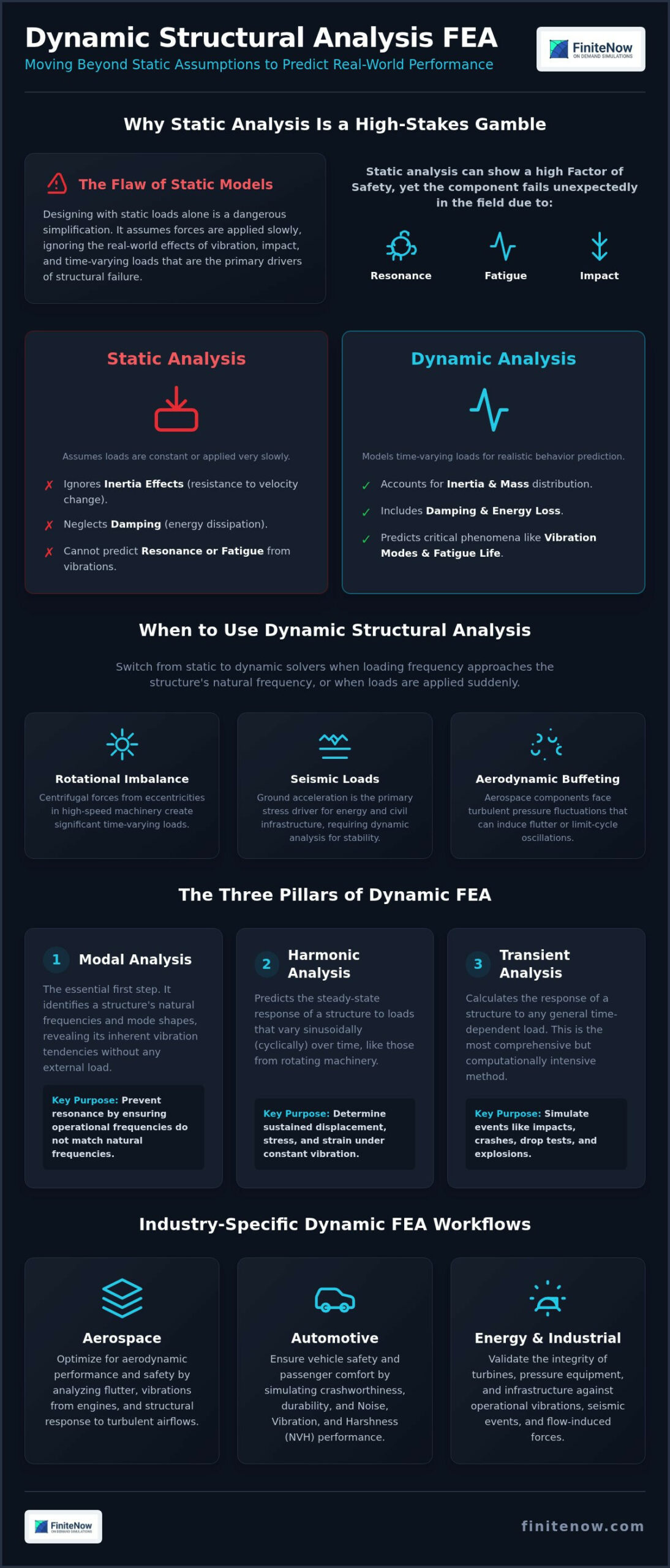
Identifying when to switch from static to dynamic solvers is a critical engineering decision. You should trigger a dynamic structural analysis FEA workflow whenever the loading frequency approaches the natural frequency of the assembly or when loads are applied suddenly. Common industrial triggers include:
- Rotational imbalance: Even minor eccentricities in high-speed industrial machinery create significant centrifugal forces that vary with time.
- Seismic loads: For energy infrastructure, ground acceleration is the primary driver of stress, requiring a deep understanding of Structural dynamics to ensure stability.
- Aerodynamic buffeting: Aerospace components face turbulent pressure fluctuations that can induce flutter or limit-cycle oscillations.
In these scenarios, static approximations don’t just provide less accuracy; they provide the wrong answer. Moving to a dynamic framework ensures your engineering reports are validated against the actual physics the hardware will encounter.
The Three Pillars of Dynamic Structural Analysis FEA
Dynamic simulation isn’t a monolithic process. It branches into three distinct methodologies: Modal, Harmonic, and Transient analysis. Selecting the correct path depends entirely on the frequency content and duration of your applied loads. Choosing the wrong solver doesn’t just waste compute cycles; it can obscure the specific vibration modes that lead to structural failure. Mastering dynamic structural analysis FEA requires a strategic understanding of when to simplify and when to commit to full time-history simulations.
Modal Analysis: The Foundation of Dynamics
Modal analysis is the essential first step for any moving assembly. It identifies the natural frequencies and mode shapes of a structure in a “free” or constrained state without external load application. If your operational environment introduces loads that match these frequencies, resonance occurs. This leads to rapid fatigue or immediate structural collapse. Modal results act as a filter for all subsequent studies. You can’t execute a precise harmonic or transient study without first identifying which modes are dominant. Boundary conditions are critical here. A minor change in bolt pre-tension or support stiffness can shift natural frequencies by several hertz, potentially moving a safe component into a dangerous resonance zone.
Harmonic and Transient Workflows
Harmonic analysis predicts steady-state behavior under constant cyclic loads. It’s the standard for rotating equipment, such as turbines or motors, where the excitation frequency is known and consistent. Because it operates in the frequency domain, it’s computationally efficient for long-duration vibrations. It provides a clear picture of peak displacements and stresses across a range of frequencies, allowing for rapid design iterations to avoid resonance peaks.
Transient analysis is the high-fidelity approach for time-history response. It’s necessary for arbitrary, non-periodic loads like crash impacts, drop tests, or seismic events. Unlike harmonic analysis, transient solvers work in the time domain, calculating the response at every discrete time step. This makes it resource-intensive but vital for capturing the complex interactions of inertia and damping during a sudden event. The computational trade-off is clear: frequency domain solvers offer speed for repetitive cycles, while time domain solvers provide the data needed for safety-critical impacts. For teams looking to bypass the technical bottlenecks of local hardware, leveraging on-demand structural simulation ensures these complex studies are completed with precision and speed.
Linear vs. Nonlinear Dynamic Analysis: Navigating Complexity
Linear dynamic models are the industry baseline. They assume small displacements, constant stiffness matrices, and purely elastic material behavior. This approach is efficient for high-cycle fatigue or low-amplitude vibrations where the structure returns to its original state. However, real-world physics often pushes components past these ideal boundaries. When your design faces extreme loads, you must transition to dynamic structural analysis FEA that accounts for changing geometry and material states.
Choosing nonlinear structural analysis becomes mandatory when loads cause large deformations or permanent set. In these cases, the stiffness of the assembly changes as it moves. A linear solver will under-predict stress or over-predict stability because it can’t “see” the shifting load paths. High-fidelity results require a balance between this technical depth and your project’s commercial constraints. Over-specifying nonlinearity can bloat budgets; under-specifying it can lead to field failure.
Material and Geometric Nonlinearities
In impact events, material nonlinearity is the primary driver of accuracy. Simulating plastic deformation allows you to visualize how energy is absorbed during a crash or drop test. Without modeling the yield curve, you can’t accurately predict residual stresses or permanent deformation. Geometric nonlinearity is equally critical for thin-walled aerospace structures. As these components deflect, they often experience “geometric stiffening,” where the tension in the skin significantly alters the vibration response. The Bauschinger effect describes the reduction in yield strength in compression following a previous tensile plastic deformation during cyclic loading. Capturing this specific phenomenon is vital for predicting the lifecycle of components under reversing dynamic loads.
Contact Dynamics and Damping
Dynamic assemblies rarely move in isolation. Modeling the friction and sliding between parts during a high-speed event is one of the most difficult aspects of dynamic structural analysis FEA. Contact nonlinearities introduce sudden changes in stiffness that can cause solver instability if handled incorrectly. You need precise algorithms to manage the energy transfer between colliding surfaces without causing artificial numerical noise.
Damping is the second half of the equation. In transient simulations, Rayleigh damping is the standard method for representing energy dissipation. It uses a combination of mass-proportional and stiffness-proportional factors to stabilize the response. Managing convergence issues in these complex assemblies requires more than raw compute power; it requires an expert understanding of solver settings and mesh density. We focus on providing these high-fidelity insights without the overhead of traditional engineering departments, ensuring your nonlinear reports are both rapid and validated.
Industry-Specific Dynamic FEA Workflows
Physics is universal, but the application of dynamic structural analysis FEA differs wildly across verticals. Aerospace engineers prioritize weight reduction and vibration stability. Automotive teams focus on crashworthiness and NVH. Industrial machinery requires long-term fatigue prediction. Medical device designers must validate implants against physiological cycles. Understanding these specific requirements is the difference between a generic simulation and a validated engineering report that stakeholders can trust.
Aerospace and Automotive Requirements
Turbine blades represent one of the most demanding environments for dynamic analysis. You must differentiate between High-Cycle Fatigue (HCF) and Low-Cycle Fatigue (LCF). HCF is driven by high-frequency vibrations during steady-state flight; LCF is triggered by the extreme thermal and centrifugal stress of engine start-stop cycles. Modern solvers like Ansys 2026 R1 now include enhanced mesh morphing to optimize these blade profiles for better aerodynamic performance while maintaining structural integrity.
For automotive teams, crash simulation is the primary use case for explicit solvers. You need to manage energy absorption paths to ensure occupant safety during milliseconds of impact. Composite material dynamics add another layer of complexity. These materials exhibit anisotropic damping properties that can significantly alter the resonant response of lightweight structural designs. Leveraging GPU acceleration for Abaqus 2026/Explicit allows these high-fidelity crash models to be solved with the speed required by agile development cycles.
Machinery, Medical, and Energy
Industrial machinery focuses on vibration isolation to protect precision components. Excessive oscillation doesn’t just cause noise; it destroys bearings and misaligns optics. In the energy sector, wind turbine components face fluctuating wind loads that induce complex aerodynamic buffeting. You must simulate these time-varying forces to ensure the structural integrity of the mast and blades over a 20-year lifespan. This requires capturing the interaction between the structure and the fluid environment.
Medical device validation requires a unique focus on biomechanics. Implants like heart valves or orthopedic plates must survive millions of physiological dynamic loading cycles. Modeling stent fatigue life requires coupled-field analysis to account for the interaction between blood flow and the expanding structural mesh. These simulations are critical for regulatory compliance and patient safety. If you’re ready to move beyond slow, traditional engineering cycles, you can get an instant quote for your FEA project and access expert-led dynamic simulations today.
Optimizing Dynamic FEA Execution: On-Demand Expertise
Traditional simulation departments often struggle with two barriers: the exorbitant cost of specialized software and a lack of niche expertise for complex transient events. Maintaining a full suite of solvers for dynamic structural analysis FEA is a significant capital expenditure that rarely aligns with fluctuating project demands. We’ve disrupted this model by offering a strategic shift from heavy software licensing to on-demand simulation. It’s a move that allows your team to access high-fidelity results without the overhead of annual maintenance fees or high-performance computing hardware.
Our German-based engineering team specializes in translating complex system dynamics into actionable data. Whether you’re analyzing a single vibrating bracket or a full multibody assembly, our workflow scales with your requirements. Instant quotes remove the friction from the R&D bidding phase. You can move from concept to validated simulation in days; you aren’t waiting weeks for a proposal.
The ROI of Outsourced Engineering Analysis
The “shelfware” problem is a silent drain on engineering budgets. Many firms pay for advanced dynamic solvers they only use a few times a year. Outsourcing your dynamic structural analysis FEA eliminates this waste. You gain immediate access to PhD-level analysts who understand the nuances of Rayleigh damping and contact convergence. This expertise ensures that your models aren’t just colorful pictures. They’re validated engineering assets. Parallelized project execution further reduces time-to-market. It allows you to run multiple design iterations simultaneously without hitting internal resource ceilings.
Integrating Simulation into Modern Procurement
Modern procurement demands transparency. Legacy consulting firms often hide their process behind opaque hourly rates and vague timelines. We’ve replaced this with a streamlined, project-based fee structure that prioritizes clarity. Our digital platform facilitates faster iteration cycles. It keeps your stakeholders informed through every step of the validation process. By leveraging a specialized team, you ensure every report meets the rigorous standards of your specific industry vertical. This agile approach doesn’t just solve technical problems. It optimizes the entire engineering lifecycle, making high-performance simulation accessible to every project manager.
Accelerating Structural Validation with Precision Dynamics
Modern engineering demands more than static safety factors. It requires a deep understanding of how assemblies respond to fluctuating loads and sudden impacts. By mastering the pillars of Modal, Harmonic, and Transient solvers, you ensure your designs survive the specific vibration profiles of their operational environment. Transitioning to dynamic structural analysis FEA that accounts for material and geometric nonlinearities is no longer an optional luxury for high-end aerospace. It’s a prerequisite for any robust mechanical assembly facing real world stress.
You don’t need to navigate these technical complexities alone or absorb the high cost of software licensing. Our expert German engineering team provides high-fidelity simulations with transparent, project-based pricing and no long-term contracts. We remove the traditional barriers to entry, allowing you to focus on innovation while we handle the technical validation. This agile model ensures you get the precision you need without the legacy overhead of internal simulation departments.
Ready to optimize your design cycle? Get an instant quote for your Dynamic FEA project and start building with data-backed confidence.
Frequently Asked Questions
What is the difference between static and dynamic FEA?
Static analysis treats loads as constant or slowly applied, ignoring the effects of inertia and damping. Dynamic analysis is required when loads change rapidly over time, making the structure’s mass and velocity critical to the result. Dynamic structural analysis FEA provides a more accurate representation of real-world performance by capturing how energy moves through an assembly, especially when loading frequencies approach the structure’s natural frequencies.
How do I know if my project requires transient dynamic analysis?
Transient analysis is necessary for non-periodic, arbitrary loads such as sudden impacts, explosions, or seismic events. You should select this method if the duration of the load is short compared to the natural period of the structure or if the loading profile is highly irregular. While computationally more intensive than harmonic studies, transient dynamics capture the precise time-history response needed for safety-critical validation and crashworthiness assessments.
Can dynamic FEA predict the fatigue life of a vibrating component?
Yes, it’s the standard method for determining durability in high-cycle environments. By calculating the stress amplitudes at every point in the vibration cycle, analysts can apply Rainflow cycle counting and S-N curves to estimate fatigue life. This process identifies potential crack initiation sites caused by resonance or repetitive cyclic loading, allowing you to optimize geometry before committing to expensive physical durability testing or manufacturing.
What information is needed to get an instant quote for dynamic analysis?
To use our instant quoting system, you need to provide the 3D CAD geometry of your assembly along with specific material properties. You must also define the loading conditions, such as the frequency range for harmonic studies or the time-history profile for transient events. Providing clear boundary conditions and damping requirements ensures our German-based engineering team can deliver a precise, project-based fee for your dynamic structural analysis FEA without delay.
Is linear dynamic analysis sufficient for automotive vibration testing?
Linear analysis is suitable for basic NVH (Noise, Vibration, and Harshness) testing where displacements are small and materials stay within the elastic range. However, it’s insufficient for crash simulations or durability tests involving material yielding and large deformations. In these scenarios, nonlinear dynamic solvers are required to account for shifting load paths and permanent deformation, ensuring the engineering report accurately reflects the vehicle’s structural integrity during extreme events.
How does damping affect the results of a dynamic simulation?
Damping is the primary mechanism for energy dissipation in a vibrating system. It significantly impacts the amplitude of the structural response, particularly near resonant frequencies. In a simulation, damping prevents oscillations from growing infinitely, providing a realistic view of how a structure settles after an excitation. Incorrectly modeling damping can lead to over-predicted stress levels or, conversely, hide critical failures by artificially suppressing the physical response of the assembly.
Can dynamic FEA replace physical drop testing for consumer electronics?
Simulation can significantly reduce the number of physical drop tests required by identifying failure modes early in the R&D phase. While some regulatory bodies still require a final physical validation, FEA provides internal stress and strain data that physical sensors can’t capture. This allows engineers to iterate on internal mounting designs and material choices rapidly, ensuring the final physical prototype passes its certification test on the first attempt.
What industry standards govern dynamic structural validation?
Dynamic validation is governed by several international and sector-specific codes. ISO 10303-209 provides the framework for multidisciplinary analysis data exchange, while ASME codes like Section VIII address pressure equipment under dynamic load. Aerospace teams often follow CS-25 or FAR-25 requirements for vibration and gust loads. Adhering to these standards ensures that your simulation reports are legally defensible and meet the rigorous safety requirements of modern procurement processes.
Simulation Work Reinvented